I dont think i have x2 wiring but most 2 stroke engines are simple. It actually fires during the exhaust stroke too.
Tm racing tm 2 stroke 125 pdf user manuals.

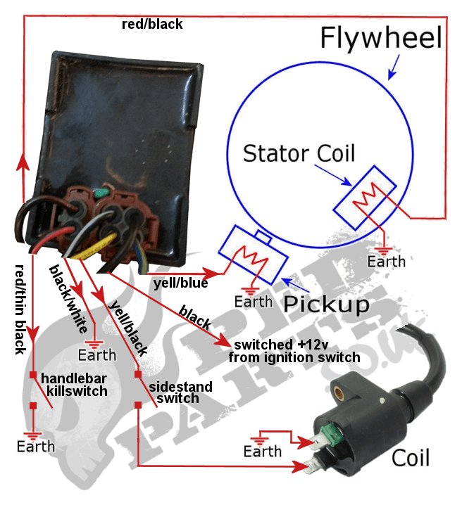
You can find out more Diagram below
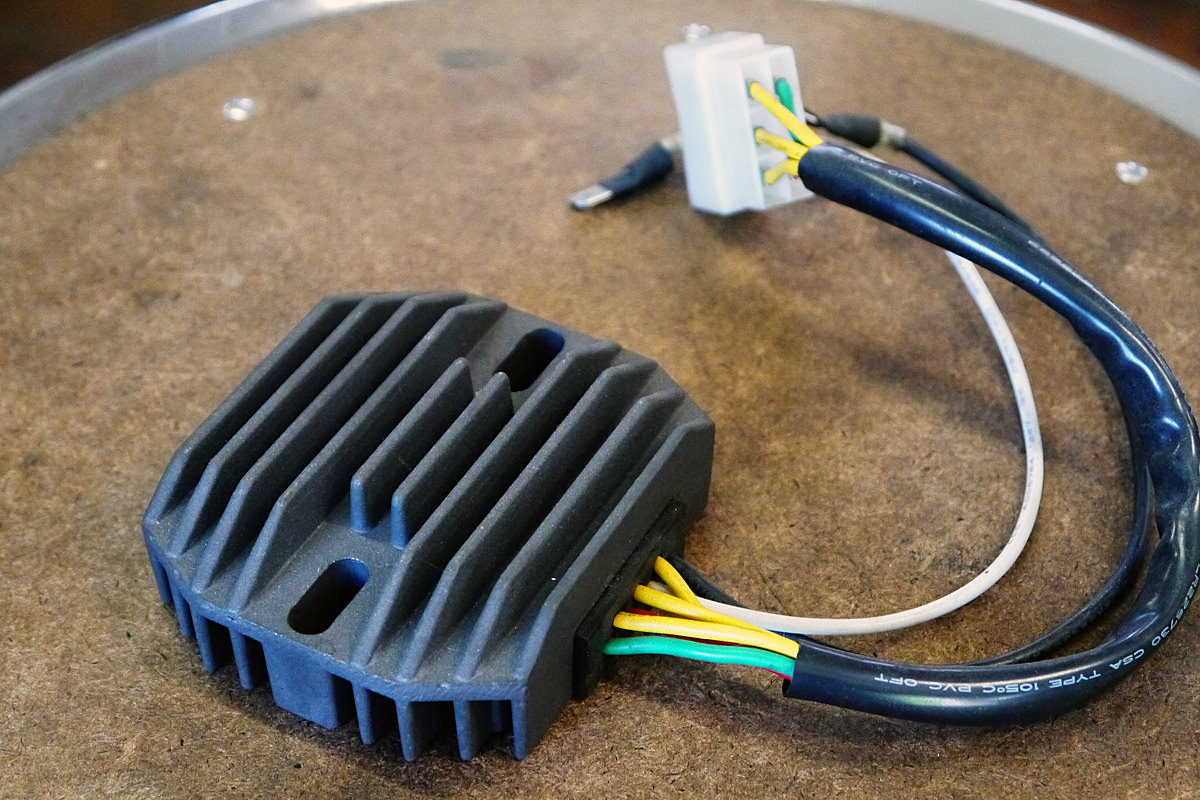
2 stroke racing wiring diagram. 01 shows a yellow brown and white wire going into the regulator plus a ground. Yamaha outboard wiring diagram awesome tohatsu 30hp wiring diagram. Mine is fairly small about 2 square but yours may be larger.
Yamaha outboard wiring diagram inspirational yamaha 703 remote. If you have a 2 stroke 49cc piston port engine there is no wiring you ground the coil thru a button to stop the engine. I dont own a x1 or x2 bike.
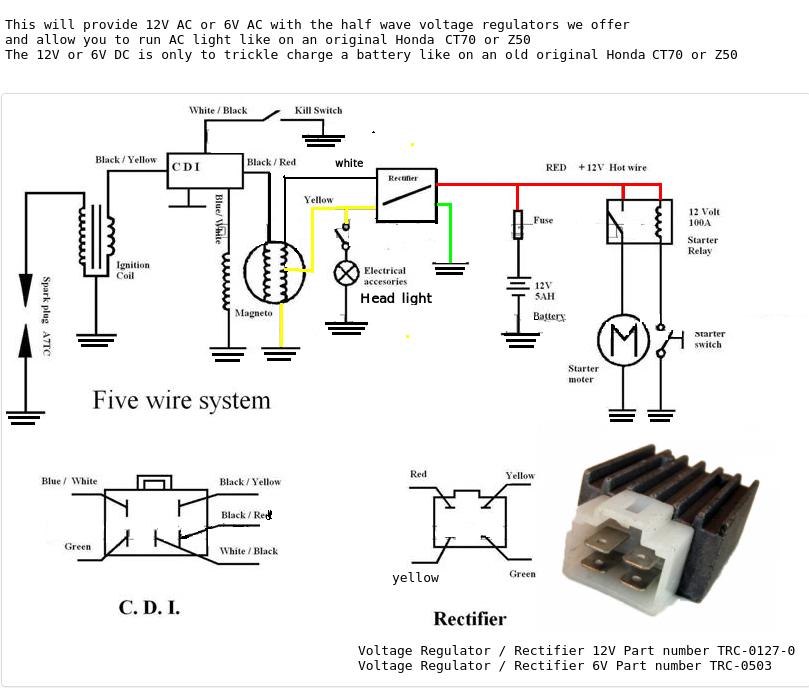
Most of the wiring you see with cateye and x bikes with lights blinkers and a battery to charge and all the other junk they put on. Theres a 2 stroke wiring diagram which seems to illustrate a 5 connector cdi. The left side is the 2000 polaris sportsman 500 early wiring diagram and the right side is the 2000 polaris sportsman 500 late.
All the lawn mowers i grew up with had a magneto with the magnet on the flywheel with the spark wire going right to the plug and a switch attached to the throttle to short some turns to kill the motor. Yamaha outboard wiring diagram inspirational yamaha 703 remote. Diagram shows 4 wires.
You have to have a rectifierregulator between the 12v power cable off your starter housing in between your battery for charging the rect. The late wiring diagram for 2000 is more than likely either the same or extremely close to the 2001. The regulator should be under the tank close to the steering head on the backbone.
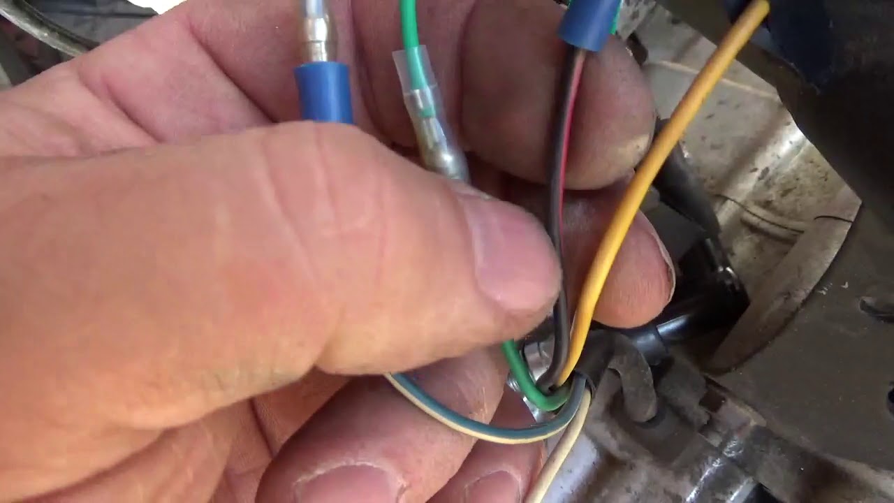
High performance racing cdi for yamaha jog zuma 2 stroke minarelli 1e40qmb engines found in a variety of scooters and atvs. Also while your at it why not cable tie your wires to the frame. Black red redwhite seem to tie in with stator wires.
Happytime 2 cycle ignition circuit explained with diagram. Turn ac into dc current to charge your battery and run any lights. Makes a stronger spark and increases throttle response for better acceleration out of the cornersthis cdi box enhancements include duplicator circuits increased rpm redline and altered ignition curves.
View online or download tm racing tm 2 stroke 125 user and maintenance manual. Now fix the red wire of the kill switch onto the frame by using the top bottle holder screw and the wiring is complete. A couple of the colours are different but the black does seem to tie in with earth and seems to be on a 2 connector plug with the coil wire which would point to the orange being coil.
Connect the bluegreen wire from the engine to the bluegreen wire of the cdi unit and then connect the black wire of the engine to the black wire of the cdi unit. My bike is a 98 and only has one wire into the regulator plus a ground. Im attaching a picture that has 2 wiring diagrams side by side.
Yamaha outboard wiring diagram pdf gallery yamaha 9 9 4 stroke wiring diagram auto electrical wiring diagram.


0 comments:
Post a Comment